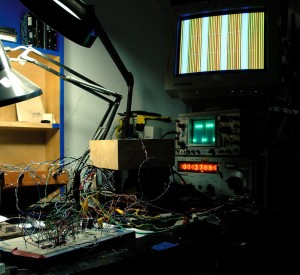
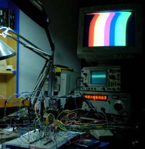
here’s my first assembly language project in the works:
i started with the program from here: “http://yusoft.kulichki.com/english/pic/my_proj.htm”:http://yusoft.kulichki.com/english/pic/my_proj.htm
it didn’t work until i added the 555 part of “this circuit”:http://yusoft.kulichki.com/english/pic/my_proj.htm in order to get the V-synch pulse-width right.
this spurred a rewrite of the program. this synched without the extra PWM stuff…
i added an extra output to function as a gate to control a 4066 switch for proper RGB blanking.
everything worked fine in the middle of the screen,
but the top of the image was skewed:
rather than try to fix this,
i moved on to making an SVGA 800×600 @ 60Hz program based on the timing info found here: “http://tinyvga.com/vga-timing/800×600@60Hz”:http://tinyvga.com/vga-timing/800×600@60Hz (and some other details elsewhere)
this runs on a 20MHz crystal which, if you do the math = exactly 100 instructions / visible line and nice round numbers for all the sync and blanking periods.
for fun i followed up with a 1024×768 @ 60Hz version:
happily this program actually worked first try, however, the skewed image thing returned.
with a lot of tuning to the Vsync areas i minimized the skew to just a small bump at the top, but i’m not sure how portable this thing would be with less forgiving monitors.
for this version i also added 75ohm terminating resisters to the RGB outputs.
i’m thinking that the ratios between vertical and horizontal sync times have a lot to do with the skewing thing. so far, this last version looks just the same whether the the processor clock is running at 18, 20, or 17.7344 MHz.
the 800×600 version has at least all the correct ratios. so next step is to use this as the core of a new AV synth.

